Actions
Esphome » Geschiedenis » Revisie 6
« Vorige |
Revisie 6/12
(diff)
| Volgende »
Micha Kersloot, 14-04-2023 20:08
Esphome
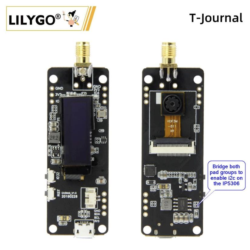
TTGO T-Journal
The T-journal is able to communicate the battery state over i2c. After bridging the pads as shown in the picter the IP5306 that is used is connected to pins 13 (scl) and 14 (sda).
working configuration:
substitutions:
  device_name: "cam01"

esphome:
  name: '${device_name}'

esp32:
 board: esp32dev
 framework:
   type: arduino

# Enable Home Assistant API
api:
  encryption:
    key: "xxxxxxxxxxxx"

ota:
  password: "xxxxxxxxxxxxx"

wifi:
  ssid: !secret wifi_ssid
  password: !secret wifi_password

  # Enable fallback hotspot (captive portal) in case wifi connection fails
  ap:
    ssid: "cam01 Fallback Hotspot"
    password: "xxxxxxx"

captive_portal:

external_components:
  - source:
      type: git
      url: https://github.com/MichaKersloot/esphome_custom_components
    components: [ ip5306, esp32_camera ]

i2c:
  - id: bus_a
    sda: 14
    scl: 13
    frequency: 400kHz
    scan: true

ip5306:
  battery_level:   # sensor
    name: '${device_name} - Battery Level'
  charger_connected:  # binary_sensor
    id: connected
    on_press:
      then:
        - lambda: ESP_LOGD("TEST", "charging");
    on_release:
      then:
        - lambda: ESP_LOGD("TEST", "not charging");
  charge_full:  # binary_sensor
    id: full
    on_press:
      then:
        - lambda: ESP_LOGD("TEST", "fully charged");
    on_release:
      then:
        - lambda: ESP_LOGD("TEST", "still charging");

esp32_camera:
  name: '${device_name} - camera'
  external_clock:
    pin: GPIO27
    frequency: 20MHz
  i2c_pins:
    sda: GPIO25
    scl: GPIO23
  data_pins: [GPIO17, GPIO35, GPIO34, GPIO5, GPIO39, GPIO18, GPIO36, GPIO19]
  vsync_pin: GPIO22
  href_pin: GPIO26
  pixel_clock_pin: GPIO21
  agc_gain_ceiling: 8x
  # jpeg_quality: 16
  # max_framerate: 25Hz
  contrast: 0
  brightness: 1
  saturation: 0
  ae_level: 2
  # aec2: True
  horizontal_mirror: false
  vertical_flip: false
  resolution: 800x600

esp32_camera_web_server:
  - port: 8080
    mode: stream
  - port: 8081
    mode: snapshot
If you are unable to program:
python -m esptool --chip esp32 --port COM5 --baud 115200 --after hard_reset erase_flashand if even that doesn't solve it:
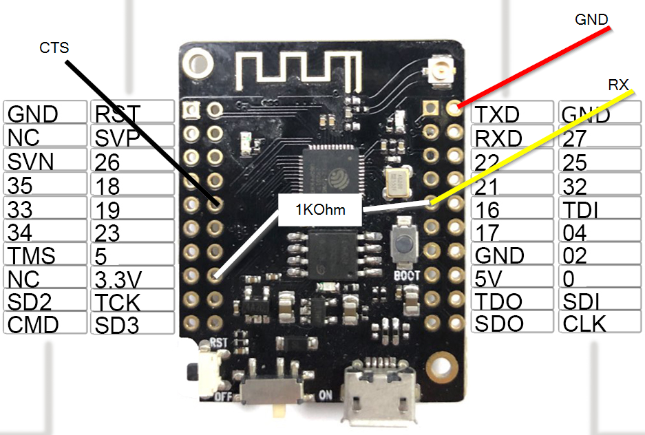
python -m esptool --port COM5 write_flash_status --non-volatile 0p1 dsmr power meter with TTGO T7 v1.3 mini
I'm using a TTGO T7 v1.3 mini with and end of a phone cable with an RJ11 connector. I soldered the connections direct to the board.

On RJ11, pin 1 and pin 6 are not connected / available
| RJ11 P1 | ESP32 Pin | 4w cable | comments |
|---|---|---|---|
| 2 - CTS | GPIO19 | black | Clear to Send, High = allow P1 Meter to send data |
| 3 - Data GND | GND | red | |
| 4 - nc | - | green | |
| 5 - RXD (data) | GPIO16 | yellow | 1K external pull-up resistor needed |

ongeveer 3 jaar geleden bijgewerkt door Micha Kersloot · 12 revisions